STMicroelectronics STM32F411DISCOVERY
The STM32F411 Discovery board offers the following features:
- STM32F411VET6 microcontroller featuring 512 KB of Flash memory, 128 KB of RAM in an LQFP100 package
- On-board ST-LINK/V2 with selection mode switch to use the kit as a standalone STLINK/V2 (with SWD connector for programming and debugging)
- Board power supply: through USB bus or from an external 5 V supply voltage
- External application power supply: 3 V and 5 V
- L3GD20, ST MEMS motion sensor, 3-axis digital output gyroscope.
- LSM303DLHC, ST MEMS system-in-package featuring a 3D digital linear acceleration sensor and a 3D digital magnetic sensor.
- MP45DT02, ST MEMS audio sensor, omnidirectional digital microphone
- CS43L22, audio DAC with integrated class D speaker driver
- Eight LEDs:
- LD1 (red/green) for USB communication
- LD2 (red) for 3.3 V power on
- Four user LEDs:
- LD3 (orange), LD4 (green), LD5 (red) and LD6 (blue)
- Two USB OTG LEDs:
- LD7 (green) VBus and LD8 (red) over-current
- Two pushbuttons (user and reset)
- USB OTG with micro-AB connector
- Extension header for LQFP100 I/Os for a quick connection to the prototyping board and an easy probing
More info about the board can be found at the product website
Hardware
The STM32F411E-DISC0 Discovery board contains the following components:
- STM32F411VET6 in LQFP100 package
- ARM® 32-bit Cortex® -M4 CPU with FPU
- 100 MHz max CPU frequency
- VDD from 1.7 V to 3.6 V
- 512 KB Flash
- 128 KB SRAM
- GPIO with external interrupt capability
- 1x12-bit, 2.4 MSPS ADC with 16 channels
- DMA Controller
- Up to 11 Timers (six 16-bit, two 32-bit, two watchdog timers and a SysTick timer)
- USART/UART (3)
- I2C (3)
- SPI/I2S (5)
- SDIO
- USB 2.0 full-speed device/host/OTG controller with on-chip PHY
- CRC calculation unit
- 96-bit unique ID
- RTC
More information about STM32F411VE can be found here:
Supported features
There are 5 GPIO controllers on the discovery board responsible for the pin usage, their configuration can be found in the header file responsible for it
Basic peripherals available in nanoFramework:
- USART 1, USART2
- I2C1, I2C3
- SPI1, SPI2
- 5 ADC channels
- I2S3
- OTG
- User Button
- 4 User LEDs
- Gyroscope
- Acceleration sensor
- Magnetic sensor
- Audio DAC
Please note that I2C1, SPI1 and I2S3 are used by the on board sensors, audio DAC and can not be used for generic use therefore I2C3 and SPI2 have been made available.
For more details on what pins the on board sensors can be addressed please refer to the board's user manual and the previous mentioned header file or the corresponding configuration file in the board's root folder.
MCU Clock usage
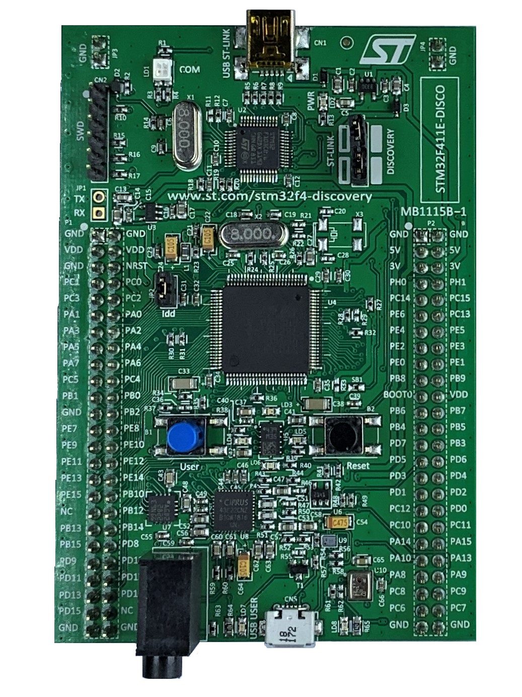
On this board there is no LSE (Low Speed External) XTal fitted. When looking at the board's picture you'll see that there is no X3 (right side and above the main MCU). In case an LSE is soldered do not forget to reflect that in the mcuconf.h files.
Serial port
There is no VCP support for the on board ST-Link/V2. That's why a seperate UART-2-USB adapter/converter has to be connected in order to communicate with Visual Studio. This is done thru nanoFramework's wire protocol which is assigned to USART2. Pins PA2, PA3 and a GND pin are needed to establish a serial connection between the discovery board and Visual Studio.
Managed helpers
Checkout the C# managed helpers available for this board.