All what you've always wanted to know about ADC
This beginner document will explain what is ADC and how to properly use it with concrete examples using .NET nanoFramework. You're in a perfect place if you want to have analogic work done and reading analogic values from a pin.
A bit of theory
An Analog-to-Digital Converter (ADC) in the realm of microcontrollers (MCU) is a fundamental component that translates analog signals, a voltage, into digital data that the MCU can understand and process. That voltag can represent a temperature or humidity coming out of an analog sensor. It enables MCU to interact with and interpret real-world analog signals, converting them into a digital format for analysis, storage, or further manipulation within the digital realm of the MCU. ADC is is opposite of Digital-to-Analog Converter (DAC).
An ADC pin is a special GPIO pin that is used only in input and can read more values than High and Low.
Important
ADC pins are able to read low current and voltage. Connecting high current and/or voltage devices may lead to destroy them! If you want to measure high voltages, you have to use a voltage divider or equivalent. This device will transform the high voltage into a smaller one. Now, be careful as the response time may be slower than what you need in the conversion.
A bit of electronics theory
Like for GPIO, the Ohms law is the one we will have to use to understand the electronics theory behind all this and how it's working.
As a reminder, Ohms law states: V = R x I.
And the typical schema used in such electronics cna be summarize as:

In this schema, we have a first fix resistor between the power and the measuring ADC pin and another variable resistor between the ADC pin and the ground. What we will then measure is the voltage at the ADC pin. This voltage will vary from VCC and Ground. So taking the example of a typical MCU, from 3.3V and 0V. Reality can be more complex as some MCU do have the ability to set different voltages for the VCC and ground for ADC. But the exact same logic will of course apply.
Applying Ohms law, you will then get:
Vpin = Rl x IVcc = Vpin + R x IVcc = (R + Rl) x I
So, in short, solving this will lead to: Vpin = Vcc / (1 + R/Rl)
This does mean that Vpin is a direct function of the variation of Rl with known elements which are R and Vcc. By convention, because it can be adjusted in some MCU, Vcc is called Reference Voltage (Vref).
Note that the variable resistor can be either on the Pull-up or Pull-down side, the reading values will just be inverted.
The electronics doing this ADC conversion is quite complex. We will not explained how it is working under the hook as it is not useful for using it.
The analogic voltage is then converted into bytes with a resolution in bits. The more precise is the ADC, the higher the resolution is. So, if you have a 8 bits resolution, you will get 256 possible values going from 0 to 255. If you have a 12 bits resolution, you will get 4096 values going from 0 to 4095.
ADC in practice
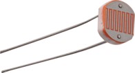
For this example, we are going to use a light sensitive analogic resistor. It typically looks like this:
And the associates schema will be:

For this specific photo resistor, its datasheet (the documentation) says the resistor varies from 1M Ω in full dark to 100 Ω in full light. The question is now, what is the best value for our R resistor from the previous equation?
A simple way, for most sensor is to apply this simple formula: R = √(Rlmax x Rlmin)
Where Rlmax is the maximum resistor of the sensor and Rlmin is the minimum one. So this will give us: R = √(1_000_000 x 100) = 10_000 Ω so 10K Ω.
Assuming our reference voltage is 3.3V, looking now at the equation and applying all those values to it: ADC pin voltage = 3.3 / (1 + 10K / Rl)
The measure voltage will go from 0.0323V (full light) to 3.23V (dark).
AdcController adc = new AdcController();
int max1 = adc.MaxValue;
int min1 = adc.MinValue;
Console.WriteLine("min1=" + min1.ToString() + " max1=" + max1.ToString());
AdcChannel ac0 = adc.OpenChannel(0);
int value = ac0.ReadValue();
double percent = ac0.ReadRatio();
Console.WriteLine("value0=" + value.ToString() + " ratio=" + percent.ToString());
Each board and MCU have different channels associated to a specific pin number. It is important to read the documentation to understand which channel is related to which pin number. Keep in mind that the number displayed on your board, the physical numbering may be different than the logical pin number which is the one used by your MCU!
How to use AdcController and AdcChannel
.NET nanoFramework exposes an AdcController which should be unique and represent an AdcController class exposing functions to mainly open and gets the channels specificities like the minimum and maximum reference voltage.
The AdcChannel represent an AdcChannel that can mainly read values, get the ratio (the percentage of of the value) and the ability to to averaging for a specific number of reads.
Note
You need to refer to the documentation of your MCU to understand which channel to use. There may not be the same number as the pin number.
ADC specific challenges
As the technology used to read convert the value and as the ADC sensors accuracy may vary, when reading one and only one value, you may have quite some error. It is then recommended to read quickly a series of values and average them to have a better value. This is possible with .NET nanoFramework and the ReadValueAveraged function.