INA219 - Bidirectional Current/Power Monitor
The INA219 is a current shunt and power monitor with an I2C- or SMBUS-compatible interface. The device monitors both shunt voltage drop and bus supply voltage, with programmable conversion times and filtering. A programmable calibration value, combined with an internal multiplier, enables direct readouts of current in amperes. An additional multiplying register calculates power in watts. The I2C- or SMBUS-compatible interface features 16 programmable addresses
- Senses Bus Voltages from 0 to 26 V
- Reports Current, Voltage, and Power
- 16 Programmable Addresses
- High Accuracy: 0.5% (Maximum) Over Temperature (INA219B)
- Filtering Options
- Calibration Registers
Documentation
This binding is intended to support both the A and B grades of the INA219. The grades differ only in the accuracy and precision specifications.
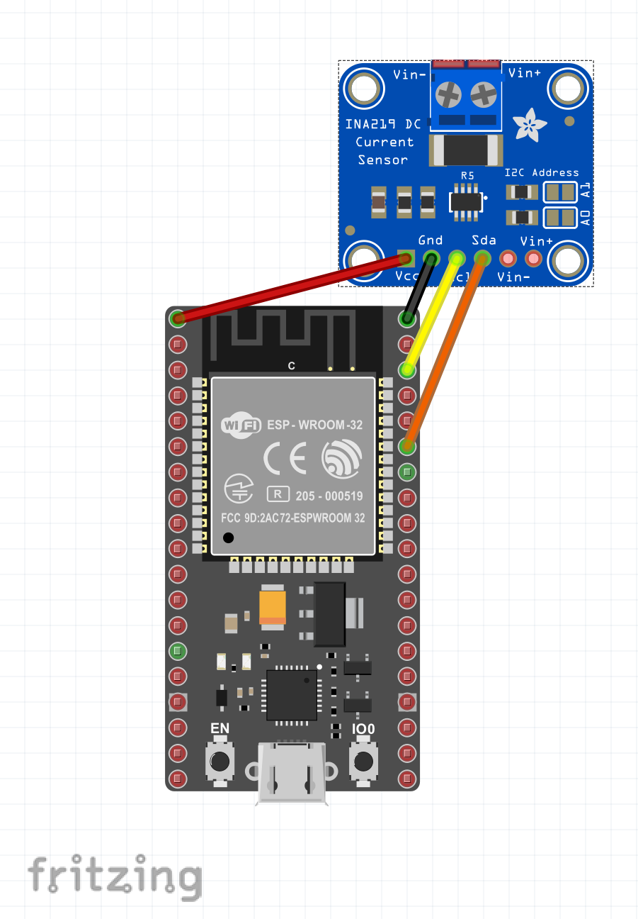
Board
Usage
const byte Ina219_I2cAddress = 0x40;
const byte Ina219_I2cBus = 0x1;

// create an INA219 device on I2C bus 1 addressing channel 64
using (Ina219 device = new Ina219(new I2cConnectionSettings(Ina219_I2cBus, Ina219_I2cAddress)))
{
    // reset the device
    device.Reset();

    // set up the bus and shunt voltage ranges and the calibration. Other values left at default.
    device.BusVoltageRange = Ina219BusVoltageRange.Range16v;
    device.PgaSensitivity = Ina219PgaSensitivity.PlusOrMinus40mv;
    device.SetCalibration(33574, (float)12.2e-6);

    while (true)
    {
        // write out the current values from the INA219 device.
        System.Console.WriteLine($"Bus Voltage {device.ReadBusVoltage()}V Shunt Voltage {device.ReadShuntVoltage() * 1000}mV Current {device.ReadCurrent() * 1000}mA Power {device.ReadPower() * 1000}mW");
        System.Threading.Thread.Sleep(1000);
    }
}
Notes
This sample uses an INA219 breakout board and monitors a LED wired into the 3.3 volts supply with a 150 ohm current limiting resistor. It prints the bus voltage, shunt voltage, current and power every second.
The configuration and calibration is determinined as follows.
- The bus voltage range can be either 16v or 32v. As this example uses a 3.3v supply then the 16v bus voltage range is chosen
- The current through the LED is in the low tens of milliamps. If we take 50mA as a reasonable maximum current that we may want to see then the maximum voltage accross the shunt resistor is 0.1 Ohms x 50mA which works out at 5mV. Given this we can use a shunt voltage range of +/- 40mV
- The maximum possible current would then be 40mV / 0.1 = 400mA
- With a 400mA maximum current and a range of the ADC of 15bits then the LSB of the current would be 400mA/32767 = 12.2207 microamps. We will chose 12.2uA as a round number.
- From the INA219 Datasheet the calibration register should be set at 0.04096/(currentLSB * shunt resistance) = 33574 = 0x8326