MBI5027 -- 16-bit shift register with error detection
MBI5027 is a 16-bit shift register. Per the datasheet, the MBI5027 is a "16-bit Constant Current LED Sink Driver with Open/Short Circuit Detection". The Mbi5027 binding is based on and is compatible with the more general ShiftRegister binding. The Mbi5027 binding adds error detection functionality. Either binding can be used to control the MBI5027.

The MBI5027 is similar to the commonly used SN74HC595 shift register, with some key differences.
- The MBI5027 has 16 inputs (and can control 16 LEDs) while the SN74HC595 has 8 outputs.
- The MBI5027 is a current sink, which means you connect the cathode (ground), not anode (power) legs, to its pins. The current comes towards the sink, not away from it. The SN74HC595 is a current source and requires the opposite wiring due to the opposite direction of current.
- The MBI5027 provides a configurable constant current, which means that resistors are not needed per input. A single resistor is used, connected to R-EXT, to configure the current.
- The MBI5027 provides the ability to detect errors, per input.
- The SN74HC595 provides a storage register clear capability, which the MBI5027 lacks.
- The MBI5027 and SN74HC595 can be controlled by the same API for their basic operations; they are protocol compatible.
Note: The MBI5168 is an 8-bit constant current sink without error detection, making it a more direct comparison to the SN74HC595.
The MBI5027 sample demonstrates how to use the shift register. The generic shift register sample is more extensive and is compatible with the MBI5027.
Documentation
- You can find the datasheet here
- Purchase: Not widely available. aliexpress.com/ was used to purchase the unit used to write this binding.
Usage
The following example code demonstrates how to use the MBI5027 with its most basic functions.
Mbi5027 sr = new(Mbi5027PinMapping.Minimal);

// Light up three of first four LEDs
sr.ShiftBit(1);
sr.ShiftBit(1);
sr.ShiftBit(0);
sr.ShiftBit(1);
sr.Latch();

// Display for 1s
Thread.Sleep(1000);

// Clear register
sr.ShiftClear();

// Write to all 16 registers with two byte values
// The `false` parameter avoids latching the storage register after the first call to `ShiftByte`
sr.ShiftByte(0b_1101_1010, false);
sr.ShiftByte(0b_1010_1101);
If you want to use SPI, see the ShiftRegister binding, which includes more information on SPI.
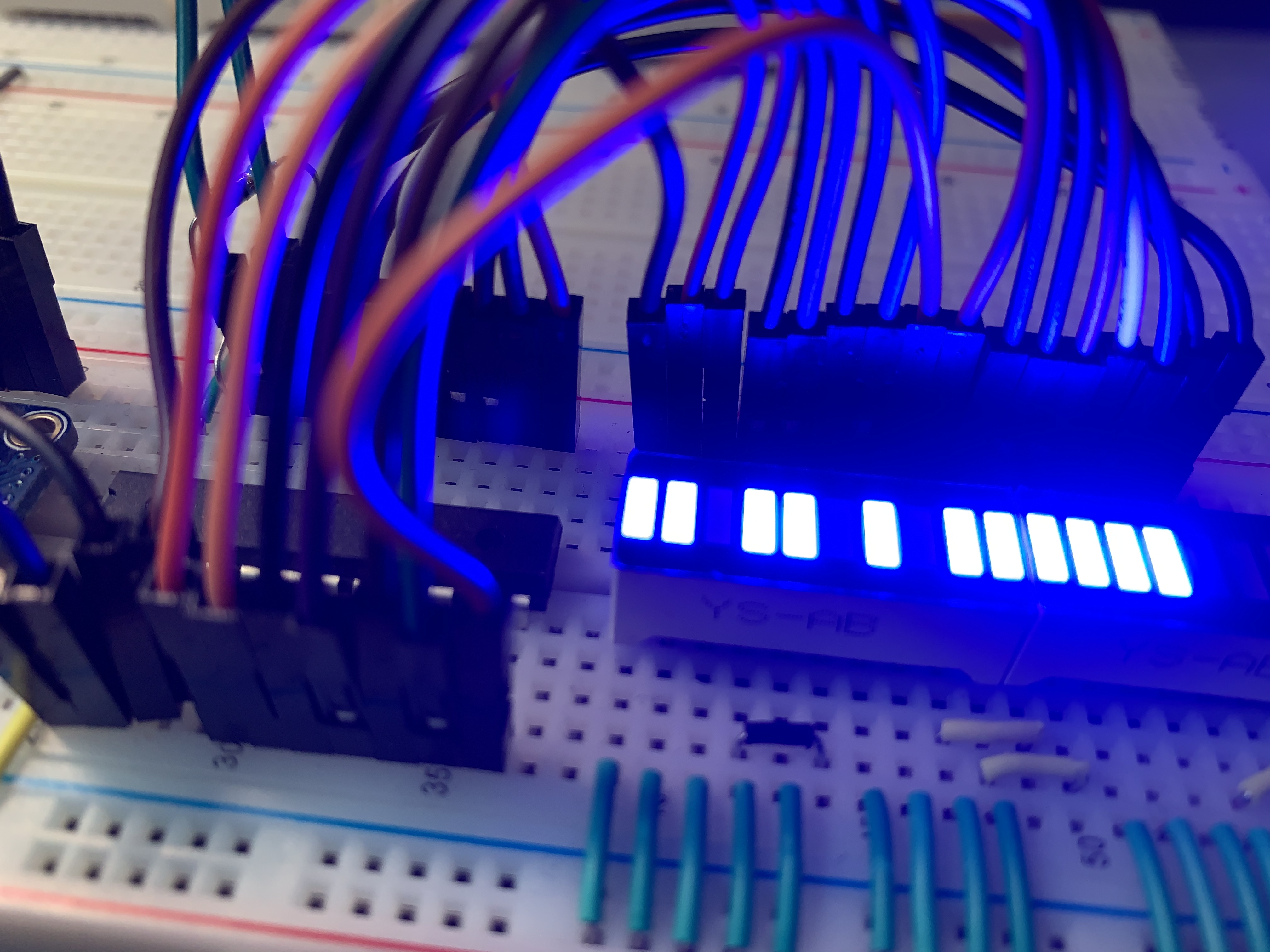
The following image demonstrate a binary clock counting example.
Example circuit
The following breadboard circuit demonstrates the correct wiring pattern, including error detection.

It is easy to mis-wire the MBI5027. The following image captures the most basic aspects for correct configuration.
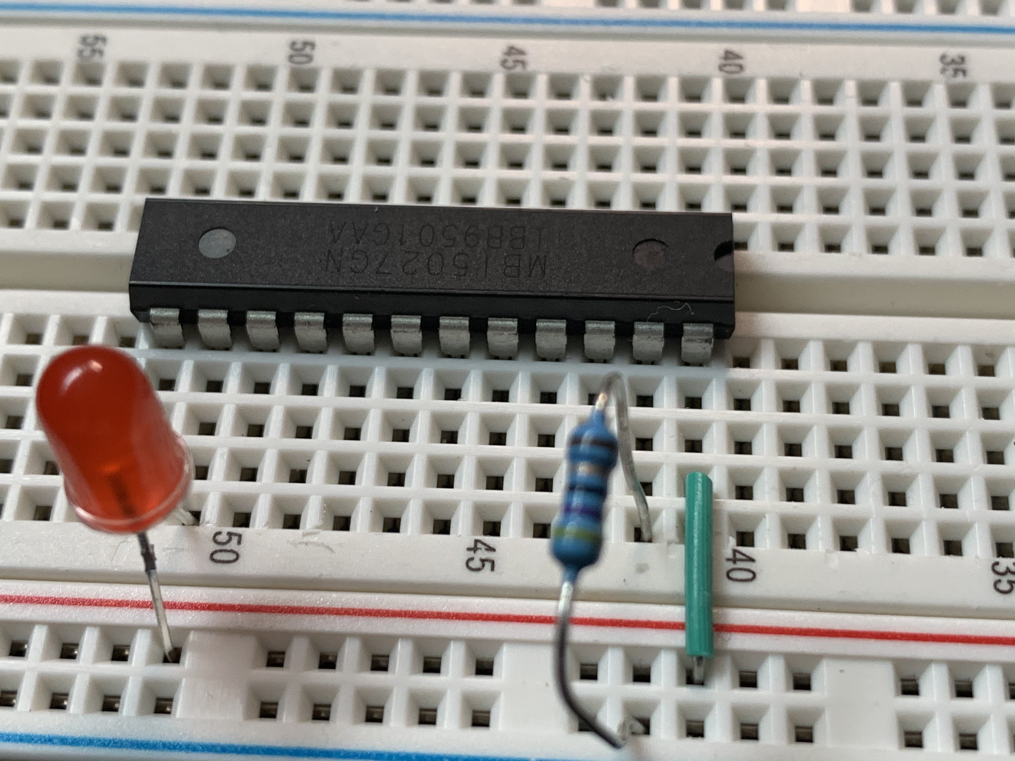
The following are key aspects to ensure are correct:
- Pin 24 (VDD) must be wired to 5v for error correction to work correctly.
- Pin 23 (R-EXT) must be connected to ground with a resistor, which configures the constant current.
- Loads must connect to the MBI5027 with their cathode legs. In this example, the LED is connected to the ground rail via its anode leg and to a MBI5027 input pin via its cathode leg.
Error detection
The MBI5027 provides the ability to detect errors, per output. This is very useful for remote deployments, to determine if repairs are required (for a traffic sign, for example). The MBI5027 requires transitioning to an error detection mode to detect errors and then back to normal mode for normal operation.
The following example code demonstrates how to detect output errors with the MBI5027.
var sr = new Mbi5027(Mbi5027PinMapping.Complete);

// switch to error detection mode
sr.EnableDetectionMode();

// read error states, per output
var index = sr.BitLength - 1;
foreach (var value in sr.ReadOutputErrorStatus())
{
    Debug.WriteLine($"Bit {index--}: {value}");
}

// switch back to normal mode
sr.EnableNormalMode();
Per the datasheet, data can be shifted into the storage register while reading the output error status and before re-entering normal mode.
When all 16 outputs are in use, and no errors are detected, you will see the following output given this code. A Low state would be shown if the output is unused, is misconfigured or other error condition. You can create this situation by disconnecting one of the input connections on the MBI5027.
Bit 15: High
Bit 14: High
Bit 13: High
Bit 12: High
Bit 11: High
Bit 10: High
Bit 9: High
Bit 8: High
Bit 7: High
Bit 6: High
Bit 5: High
Bit 4: High
Bit 3: High
Bit 2: High
Bit 1: High
Bit 0: High
Note: Error detection was found to work only with 5v power. When 3.3v power was used, error detection did not work correctly.