MPU6050/MPU6500/MPU9250 - Gyroscope, Accelerometer, Temperature and Magnetometer (MPU9250 only)
MPU6050/MPU6500 are 3 axis Gyroscope, 3 axis Accelerometer and Temperature sensors that can be accessed either thru I2C or SPI. This implementation is only for I2C. The sensor can be found in various implementation but its main usage is in the MPU9250.
MPU9250 is a 3 axis Gyroscope, 3 axis Accelerometer, 3 axis Magnetometer and Temperature sensor that can be accessed either thru I2C or SPI. This implementation is only for I2C. The sensor can be found in various implementation like Grove or Sparkfun. MPU9250 incorporate a MPU6500 and an AK8963.
The Magnetometer used is an AK8963. In general, it is managed thru the main MPU9250 and setup as a replica I2C. All operations go thru the MPU9250. In some cases, the AK8963 is exposed and the operations are not going thru the MPU9250 but directly.
Documentation
- Registers documentation
- Product specifications
Usage
Important: make sure you properly setup the I2C pins especially for ESP32 before creating the I2cDevice, make sure you install the nanoFramework.Hardware.ESP32 nuget:
//////////////////////////////////////////////////////////////////////
// when connecting to an ESP32 device, need to configure the I2C GPIOs
// used for the bus
Configuration.SetPinFunction(21, DeviceFunction.I2C1_DATA);
Configuration.SetPinFunction(22, DeviceFunction.I2C1_CLOCK);
For other devices like STM32, please make sure you're using the preset pins for the I2C bus you want to use.
General case with AK8963 is not exposed (where you can't find it on the I2C bus at the address 0x0C)
var mpui2CConnectionSettingmpus = new I2cConnectionSettings(1, Mpu9250.DefaultI2cAddress);
Mpu9250 mpu9250 = new Mpu9250(I2cDevice.Create(mpui2CConnectionSettingmpus));
In case the AK8963 is exposed, so you can reach it directly, you can then use the following code:
var mpui2CConnectionSettingmpus = new I2cConnectionSettings(1, Mpu9250.DefaultI2cAddress);
using Mpu9250 mpu9250 = new Mpu9250(I2cDevice.Create(mpui2CConnectionSettingmpus), i2CDeviceAk8963: I2cDevice.Create(new I2cConnectionSettings(1, Ak8963.DefaultI2cAddress)));
You can find an example in the sample directory. Usage is straightforward including the possibility to have a calibration for all sub sensors.
var mpui2CConnectionSettingmpus = new I2cConnectionSettings(1, Mpu9250.DefaultI2cAddress);
Mpu9250 mpu9250 = new Mpu9250(I2cDevice.Create(mpui2CConnectionSettingmpus));
var gyro = mpu9250.GetGyroscope();
Debug.WriteLine($"Gyro X = {gyro.X, 15}");
Debug.WriteLine($"Gyro Y = {gyro.Y, 15}");
Debug.WriteLine($"Gyro Z = {gyro.Z, 15}");
var acc = mpu9250.GetAccelerometer();
Debug.WriteLine($"Acc X = {acc.X, 15}");
Debug.WriteLine($"Acc Y = {acc.Y, 15}");
Debug.WriteLine($"Acc Z = {acc.Z, 15}");
Debug.WriteLine($"Temp = {mpu9250.Temperature.Celsius.ToString("0.00")} °C");
var magne = mpu9250.ReadMagnetometer(true);
Debug.WriteLine($"Mag X = {magne.X, 15}");
Debug.WriteLine($"Mag Y = {magne.Y, 15}");
Debug.WriteLine($"Mag Z = {magne.Z, 15}");
Self-test
A self-test is available for the gyroscope and the accelerometer.
var resSelfTest = mpu9250.RunGyroscopeAccelerometerSelfTest();
Debug.WriteLine($"Self test:");
Debug.WriteLine($"Gyro X = {resSelfTest.Item1.X} vs >0.005");
Debug.WriteLine($"Gyro Y = {resSelfTest.Item1.Y} vs >0.005");
Debug.WriteLine($"Gyro Z = {resSelfTest.Item1.Z} vs >0.005");
Debug.WriteLine($"Acc X = {resSelfTest.Item2.X} vs >0.005 & <0.015");
Debug.WriteLine($"Acc Y = {resSelfTest.Item2.Y} vs >0.005 & <0.015");
Debug.WriteLine($"Acc Z = {resSelfTest.Item2.Z} vs >0.005 & <0.015");
The returned data are the raw data and allows you to estimate the quality of the test. The first item of the tuple is the gyroscope and the second one the accelerometer.
No self-test is available for the magnetometer.
Calibration and bias
You can calibrate the Gyroscope and the Accelerometer at the same time. This action is as well correcting the registers directly in the MPU9250 chip. Those data are lost in case of power stop but stays in case of soft reset.
Debug.WriteLine("Running Gyroscope and Accelerometer calibration");
mpu9250.CalibrateGyroscopeAccelerometer();
Debug.WriteLine("Calibration results:");
Debug.WriteLine($"Gyro X bias = {mpu9250.GyroscopeBias.X}");
Debug.WriteLine($"Gyro Y bias = {mpu9250.GyroscopeBias.Y}");
Debug.WriteLine($"Gyro Z bias = {mpu9250.GyroscopeBias.Z}");
Debug.WriteLine($"Acc X bias = {mpu9250.AccelerometerBias.X}");
Debug.WriteLine($"Acc Y bias = {mpu9250.AccelerometerBias.Y}");
Debug.WriteLine($"Acc Z bias = {mpu9250.AccelerometerBias.Z}");
Calibration is as well available for the magnetometer (the AK8963). For this sensor.
Debug.WriteLine("Magnetometer calibration is taking couple of seconds, please be patient!");
Debug.WriteLine("Please make sure you are not close to any magnetic field like magnet or phone. Move the sensor in all possible directions");
var mag = mpu9250.CalibrateMagnetometer();
Debug.WriteLine($"Correction factor bias:");
Debug.WriteLine($"Mag X = {mpu9250.MagnometerBias.X}");
Debug.WriteLine($"Mag Y = {mpu9250.MagnometerBias.Y}");
Debug.WriteLine($"Mag Z = {mpu9250.MagnometerBias.Z}");
See AK8963 calibration for more information on how Magnetometer calibration is working. Please note that you have a full code sample to read and save data in a file to go deeper into the Magnetometer calibration.
Note: AK8963 calibration must be performed before other calibrations and before using any other part of the sensors.
Units
Al axis are oriented this way:
+Z +Y
\ | /
\ | /
|/
/|
/ |
/ |
+X
Gyroscope
The unit used for the gyroscope are degree per seconds.
Accelerometer
The unit used for the accelerometer is G.
Magnetometer
The unit used for the magnetometer is µTesla.
Temperature
The Temperature is a normalized Units.Temperature which can provide Celsius, Kelvin or Fahrenheit degrees.
Measurement modes
The MPU9250 offers a large variety of measurement modes. They can be changed and adjusted thru the properties like:
MagnetometerMeasurementModeto adjust the type of measurement for the magnetometerMagnetometerOutputBitModeto select between 14 and 16 bits precision of the magnetometerAccelerometerRangeto adjust the range of the accelerometer between 2, 4, 8 or 16 GAccelerometionScaleto adjust the frequency of measurement from 5 Hz to 1130 HzGyroscopeRangeto adjust the range of the gyroscope from 250, 500, 1000 and 2000 degrees per secondGyroscopeScaleto adjust the frequency of measurement from 5 Hz to 8800 HzSampleRateDividerallows you to reduce the number of samples for the gyroscope and the accelerometer. This feature is only available for some of the bandwidth modes.DisableModesallows you to disable any of the gyroscope and accelerometer axis
Wake on motion
A unique SetWakeOnMotion mode is available. It puts the MPU9250 in a low consumption, low measurement rate mode and trigger an interruption on the INT pin.
mpu9250.SetWakeOnMotion(300, AccelerometerLowPowerFrequency.Frequency0Dot24Hz);
// You'll need to attach the INT pin to a GPIO and read the level. Once going up, you have
// some data and the sensor is awake
// In order to simulate this without a GPIO pin, you will see that the refresh rate is very low
// Setup here at 0.24Hz which means, about every 4 seconds

while (true)
{
    var acc = mpu9250.GetAccelerometer();
    Debug.WriteLine($"Acc X = {acc.X, 15}");
    Debug.WriteLine($"Acc Y = {acc.Y, 15}");
    Debug.WriteLine($"Acc Z = {acc.Z, 15}");
    Thread.Sleep(100);
}
FIFO mode
The Fifo mode allows you to get the data by batch. You can select the mode thru FifoModes, then read the FifoCount property. You can then read the data thru ReadFifo Make sure you'll size the Span<byte> with FifoCount length.
Data are in the order of the Register from 0x3B to 0x60 so you'll get your data in this order:
- ACCEL_XOUT_H and ACCEL_XOUT_L
- ACCEL_YOUT_H and ACCEL_YOUT_L
- ACCEL_ZOUT_H and ACCEL_ZOUT_L
- TEMP_OUT_H and TEMP_OUT_L
- GYRO_XOUT_H and GYRO_XOUT_L
- GYRO_YOUT_H and GYRO_YOUT_L
- GYRO_ZOUT_H and GYRO_ZOUT_L
- EXT_SENS_DATA_00 to EXT_SENS_DATA_24
It is then up to you to transform them into the correct data. You can multiply your raw data by AccelerometionScale and GyroscopeScale to convert them properly.
I2C replica primitives
2 primitive functions allow to read and write any register in any of the replica devices.
I2cWrite(I2cChannel i2cChannel, byte address, byte register, byte data)- i2cChannel: The replica channel to attached to the I2C device
- address: The I2C address of the replica I2C element
- register: The register to write to the replica I2C element
- data: The byte data to write to the replica I2C element
I2cRead(I2cChannel i2cChannel, byte address, byte register, SpanByte readBytes)- i2cChannel: The replica channel to attached to the I2C device
- address: The I2C address of the replica I2C element
- register: The register to write to the replica I2C element
- readBytes: The read data
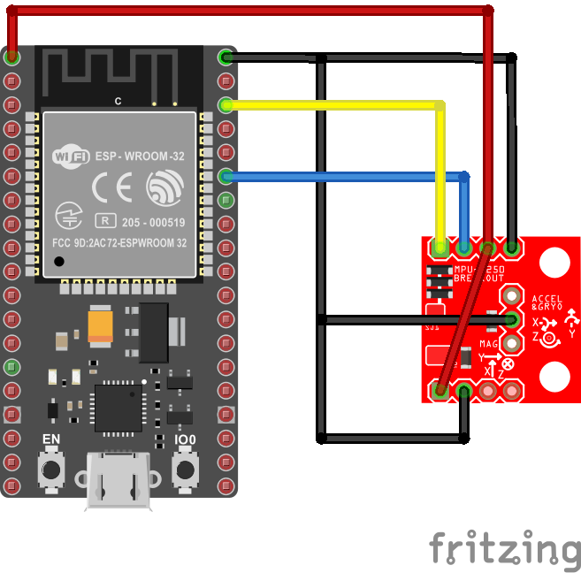
Circuit
The following fritzing diagram illustrates one way to wire up the MPU9250 with a MCU like ESP32 using I2C.